AIR COOLING
For conventional or moderate-density compute environments.
Prefabricated Compute Capacity.
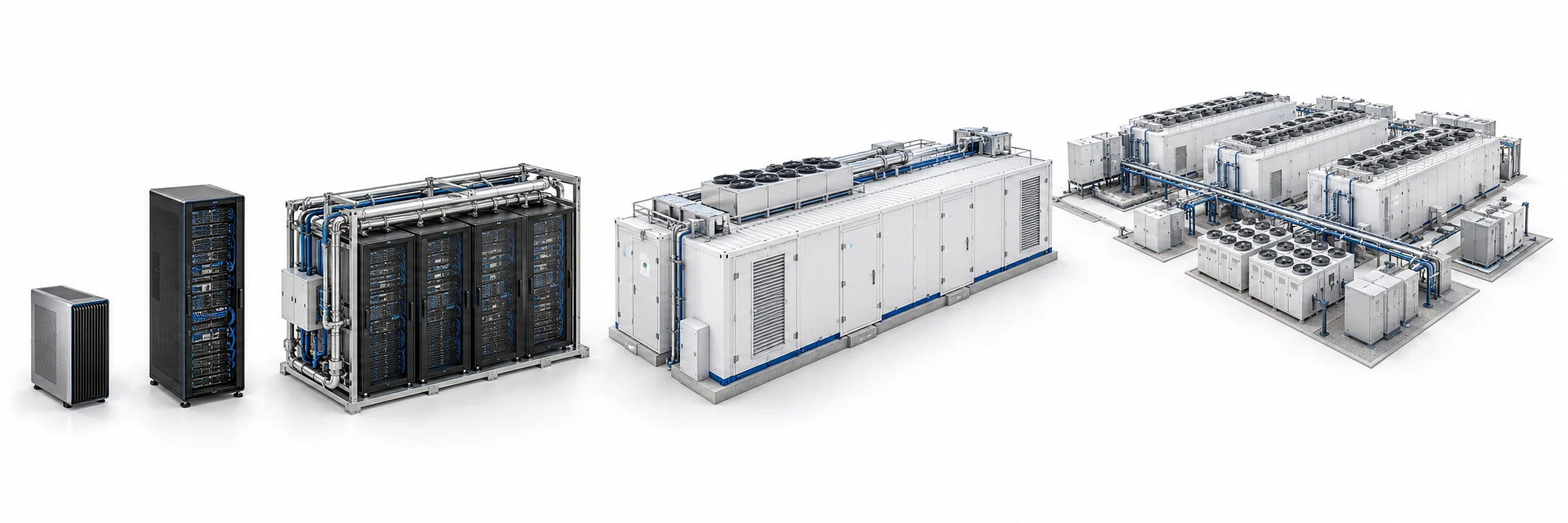
Containerized or prefabricated AI data-center infrastructure integrating IT racks with the systems required to operate them.
Containerized or prefabricated AI data-center infrastructure integrating IT racks with the systems required to operate them.
For conventional or moderate-density compute environments.
For higher-density CPU / GPU systems requiring direct component cooling.
For high-density or specialized compute environments where an integrated immersion architecture is appropriate.
Final cooling architecture depends on the selected accelerator, server design, rack density, environment and operating requirements.
Cooling selection follows validated server and accelerator architecture.
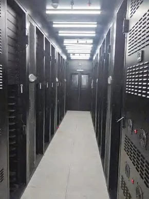
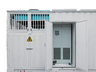
Numbered system zones show how the reference architecture fits together.
IT racks · 42U / 47U / 52U reference rack-space options
CONFIGURATION-DEPENDENTPrecision distribution · Integrated distribution · PDU
S1 CAPABILITYRack UPS · Modular UPS
CONFIGURATION-DEPENDENTAir cooling · Row cooling · Indirect evaporative cooling
CONFIGURATION-DEPENDENTLead-acid battery option · Lithium battery option
CONFIGURATION-DEPENDENTPower and environmental monitoring · Security monitoring · Energy management
S1 CAPABILITYEarly detection · Smoke and temperature detection · Fire suppression · Pressure relief · Emergency exit
CONFIGURATION-DEPENDENTFunctional cutaway schematic. Final zone placement and service access depend on configuration.
Compact modular data-center format
Standard modular data-center format
Extended modular format
Reference enclosure formats; dimensions, internal layout and delivered equipment are configuration-dependent.
Compact modular capacity.
Standard modular AI data-center format.
Extended modular capacity.
Configuration depends on workload and site requirements.
UPS, batteries, distribution and cooling are selected for the exact IT configuration and site. Ratings and thermal limits are not universal.
12.5 / 25 / 40 / 50 kW
SUPPLIER REFERENCE RANGE80 / 100 / 120 / 200 kW
SUPPLIER REFERENCE RANGECurrent reference technology includes multiple air and indirect-evaporative cooling capacity classes. Final selection follows rack density, ambient conditions and redundancy requirements.
These reference classes do not define the complete RC-4 cooling offering.
Backup path into UPS
1–200 kVA reference configurable UPS range
Current reference infrastructure supports configurable modular UPS architectures; project capacity is defined by the final IT and resilience requirement.
Modular topology and parallel expansion are reference capabilities. This range is not an absolute RC-4 limit.
Controlled physical access, environmental and security monitoring, and project-specific fire protection are integrated into the module design.
Security can be evaluated as a configurable design consideration across compute, network, data, model and agent interfaces.
Selected controls and integration scope require project-specific validation. A complete AI cybersecurity platform is not included by default.
Explore Security & GovernanceRemote Monitoring Capable
Add modules with planned utility, network and control interfaces to grow site capacity.
Configurable lifecycle support can include diagnostics, preventive maintenance, validated security updates, monitoring, modernization and expansion.
Lifecycle Support & EvolutionWarranty coverage, maintenance periods, service availability, response times, third-party licensing and upgrade scope are defined in the applicable project and service agreements.
Capabilities describe system integration. Reference configurations show an implementation path. Exact values follow project engineering. Supplier references remain provider statements.
PROJECT-VALIDATED is reserved for confirmed S1 customer configurations. No project-validated product values are published here.
| FIELD | VALUE | STATUS |
|---|---|---|
| Platform | Modular AI Data Center | S1 CAPABILITY |
| Format | 20 / 40 / 45 ft reference platforms | REFERENCE CONFIGURATION |
| Rack space | 42U / 47U / 52U reference options | CONFIGURATION-DEPENDENT |
| UPS | Modular / rack | CONFIGURATION-DEPENDENT |
| Cooling | Air / row / indirect evaporative / project-specific | CONFIGURATION-DEPENDENT |
| Battery | Lead-acid / lithium reference options | CONFIGURATION-DEPENDENT |
| Monitoring | Environmental / security / energy | S1 CAPABILITY |
| Fire | Detection / suppression architecture | CONFIGURATION-DEPENDENT |
| Protection | IP55 in current reference platform | SUPPLIER REFERENCE |
| Seismic | GR-63-CORE Zone 3 reference | SUPPLIER REFERENCE |
| FIELD | VALUE | STATUS |
|---|---|---|
| Enclosure protection | IP55 in the current reference supplier platform; configuration-dependent | SUPPLIER REFERENCE |
| Seismic | GR-63-CORE Zone 3 reference; subject to project validation | SUPPLIER REFERENCE |
Final environmental and seismic requirements must be confirmed against the exact delivered configuration and applicable project standards.
Available architecture does not establish stock availability or a project delivery date. RC-2 and RC-3 remain S1 system architectures pending a dedicated supplier configuration.
Tell us what must run, where it must run and how quickly you need capacity.
Configure Your AI InfrastructureRapid Compute focuses on deployable AI infrastructure.
Projects requiring full digital project modeling, industrial simulation, energy architecture or multi-domain infrastructure integration can continue through S1 SYSTEM.
Explore S1 SYSTEMS1 SYSTEM
Model the World. Build the System.